
- Home/
- GATE ELECTRICAL/
- GATE EE/
- Article
Study notes on Mechanical Consideration of Transmission Line Electrical Engineering
By BYJU'S Exam Prep
Updated on: September 25th, 2023

Welcome to the realm of Mechanical Considerations of Transmission Lines in Electrical Engineering, where the fusion of engineering expertise and structural principles ensures the seamless and reliable transmission of electrical power over vast distances. As an aspiring electrical engineer, delving into this field will grant you an in-depth understanding of the critical mechanical aspects involved in designing, erecting, and maintaining high-voltage transmission lines. These study notes have been meticulously curated to serve as your comprehensive guide, offering valuable insights into the structural design, material selection, and performance evaluation of transmission lines, all of which are crucial to the integrity and longevity of power networks.
Transmission lines form the backbone of electrical power distribution, carrying electricity across continents, and bridging the gap between power generation stations and consumption centres. To ensure the efficient transfer of power, it is imperative to explore the mechanical considerations that govern these towering structures. From the selection of suitable conductors and insulators to understanding the impact of environmental factors and dynamic loads, this study material will equip you with the knowledge to design robust transmission lines that can withstand the forces of nature and serve as a lifeline for societies around the world. Embrace this enriching learning experience as you embark on your journey through the Mechanical Considerations of Transmission Lines in Electrical Engineering.
Download Formulas for GATE Electrical Engineering – Electrical Machines
Table of content
Mechanical Design of Overhead Lines
The Mechanical Design of Overhead Lines is a critical aspect of electrical engineering that focuses on creating robust and reliable structures for the efficient transmission of electrical power. This field involves careful consideration of materials, structural components, and environmental factors to ensure the safe and stable operation of overhead transmission lines, which form the backbone of power distribution networks.
Sag and Tension
Supports at the Same Level
![]()
where S = Sag at mid-point in meter.
Z = Length of span in meters.
W = Conductor weight kg/m
T = Conductor tension [assumed constant over the whole span] Newton

Effect of Ice and Wind Loading
The weight of ice per unit length of the conductor,
![]()
where, p = Density of ice (910 kg/m3)
Wind Loading
Wind loading wa per unit length
= 2 (r + t) p kg/m
where, p = Wind pressure in kg/m2
r = Radius of conductor
l = Thickness of ice coating
Total loading on conductor per metre length
![]()
Spacing between conductors (without sparing)
Spacing ![]() meter.
meter.
where S = Sag in metre
V = Line voltage in kV
Supports at a different level
![]()
and ![]()
where, Ic = Span of a complete parabola.
Voltage Control: The voltage of the generator is proportional to the speed and excitation (flux) of the generator.
- Voltages at all terminals of all equipment in the system are within acceptable limits
- System stability is enhanced to maximize the utilization of the transmission system
- The reactive power flow is minimized so as to reduce RI2 and XI2 losses.
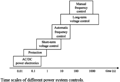
From a system point of view, the regulation of the voltage and reactive power is usually organized in three levels; primary, secondary and tertiary voltage regulation.
- The Primary Voltage Regulation (PVR) refers to the local automatic response of the controllers.
- The Secondary Voltage Regulation (SVR) is an automatic control that coordinates the actions of PVRs at a zonal level. The secondary regulation level is not implemented in all Transmission System Operators TSOs since its added cost and complication are not always justified.
- The Tertiary Voltage Regulation (TVR) refers to the manual optimization of the voltage and reactive power at a regional or national system level (area).
The regulation scheme with three levels is referred to as (i) hierarchical voltage regulation, whereas the regulation scheme without SVR is referred to (ii) Centralized Voltage Regulation (CVR).
If the system is connected to numerous loads in a power system, then the system frequency and speed change with the characteristics of the governor as the load changes. If it’s not required to maintain the frequency constant in a system then the operator is not required to change the setting of the generator. But if the constant frequency is required the operator can adjust the velocity of the turbine by changing the characteristics of the governor when required. If a change in load is taken care by two generating stations running parallel then the complex nature of the system increases. The ways of sharing the load by two machines are as
follow:
- Suppose there are two generating stations that are connected to each other by a tie line. If the change in load is either at A or at B and the generation of A is regulated so as to have constant frequency then this kind of regulation is called Flat Frequency Regulation.
- The other way of sharing the load is that both A and B would regulate their generations to maintain the frequency constant. This is called parallel frequency regulation.
- The third possibility is that the change in the frequency of a particular area is taken care of by the generator of that area thereby maintaining the tie-line loading. This method is known as flat tie-line loading control.
- In Selective Frequency control, each system in a group is taken care of the load changes on its own system and does not help the other systems, the group for changes outside its own limits.
- In Tie-line Load-bias control all the power systems in the interconnection aid in regulating frequency regardless of where the frequency change originates.
Speed Governing System
- Mathematical Modelling of a Generator
- Mathematical Modelling of Load
The load on a power system consists of a variety of electrical drives. The loading speed
characteristic of the load is given by:
ΔPe = ΔPL + D Δω
where ΔPL is the non-frequency sensitive change in load,
DΔω is the load change that is frequency sensitive.
D is expressed as % change in load divided by % change in frequency. - Mathematical Modelling of Prime Mover
The source of power generation is the prime mover. It can be hydraulic turbines near waterfalls, or steam turbines whose energy comes from the burning of coal, gas and fuels. The model of the turbine relates the changes in mechanical power output ΔPm and the changes in the steam valve position ΔPV.
![]()
where the turbine constant is in the range of 0.2 -2.0s.
- Mathematical Modelling of Prime Mover
When the electrical load is increased suddenly then the electrical power exceeds the input mechanical power. This deficiency of power on the load side is compensated by the kinetic energy of the turbine. Due to this reason, the energy that is stored in the machine is decreased and the governor sends a signal for supplying more volumes of water, steam or gas to increase the speed of the prime mover to compensate for a deficiency in speed.
![]()
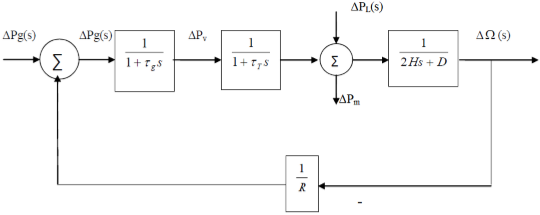
The command ΔPg is transformed through an amplifier to the steam valve position command ΔPV. We assume here a linear relationship and considering simple time constant we get this s-domain relation
![]()
Combining all the above block diagrams, for an isolated area system we get the following
Automatic Generation Control(AGC)
- If the load on the system is suddenly increased, then the speed of the turbine drops before the governor could adjust the input of the steam to this new load. As the change in the value of speed decreases the error signal becomes lesser and the position of the governor and not of the fly balls gets nearer to the point required to keep the speed constant.
- One way to regain the speed or frequency to its actual value is to add an integrator on its way. The integrator will monitor the average error over a certain period of time and will overcome the offset.
- Thus as the load in the system changes continuously the generation is adjusted automatically to restore the frequency to its nominal value. This method is known as automatic generation control.
- In an interconnected system consisting of several areas, the task of the AGC is to divide the load among the system, stations, and generators so as to achieve maximum economy
and uniform frequency.
Automatic Generation Control(AGC) in a Single Area
With the main LFC loop, a change in the system load will result in a steady state frequency deviation, depending on the speed regulation of the governor. To reduce the frequency deviation to zero we need to provide a reset action by using an integral controller to act on the load reference setting to alter the speed set point. This integral controller would increase the system type by 1 which forces the final frequency deviation to zero. The integral controller gain needs to be adjusted for obtaining a satisfactory transient response.
Automatic Generation Control(AGC) in Multi Area System

- To maintain the desired megawatt output power of a generator matching the changing load,
- To assist in controlling the frequency of larger interconnections,
- To keep the net interchange power between pool members, at the predetermined values.
If you are preparing for GATE and ESE, avail of BYJU’S Exam Prep Online Classroom Program to get unlimited access to all the live structured courses and mock tests from the following link :
- ESE and GATE ECE Online Classroom Program( Live classes and 150+ mock tests)
- ESE and GATE EE Online Classroom Program(Live classes and 193+ mock tests)
Get complete information about the GATE exam pattern, cut-off, and all those related things on the BYJU’S Exam Prep official youtube channel.


