
Reservoir and Channel Routing [GATE Notes]
By BYJU'S Exam Prep
Updated on: September 25th, 2023

Reservoir and Channel Routing is the techniques of flood routing. Flood routing provides the techniques for determining peak discharge and the pattern of the flow hydrograph for a particular flood condition. Flood routing can be carried out with different methods, known as the reservoir and channel routing techniques.
Reservoir and Channel Routing PDF(Download Notes)
Flood routing is essential for predicting the intensity of the flood in a particular catchment. With the help of predicting the flood before its occurrence, ensure to proper safety measures for the affected locality. The article contains fundamental notes on the “Reservoir and Channel Routing” topic of the “Engineering Hydrology” subject.
Table of content
What is Reservoir and Channel Routing?
Reservoir and channel routing is the techniques of flood routing; with the help of routing techniques, the estimation of the peak discharges and flood hydrograph patterns for a particular flood condition can be easily determined. With the help of these methods, flood prediction can be done easily.
Reservoir and channel routing methods are used for the determination of floods in a particular catchment basin. These two methods have common purposes but different ways of the determination of flood peak discharges and patterns of the flow. To understand reservoir and channel routing methods, first, we need to understand flood routing.
Flood Routing
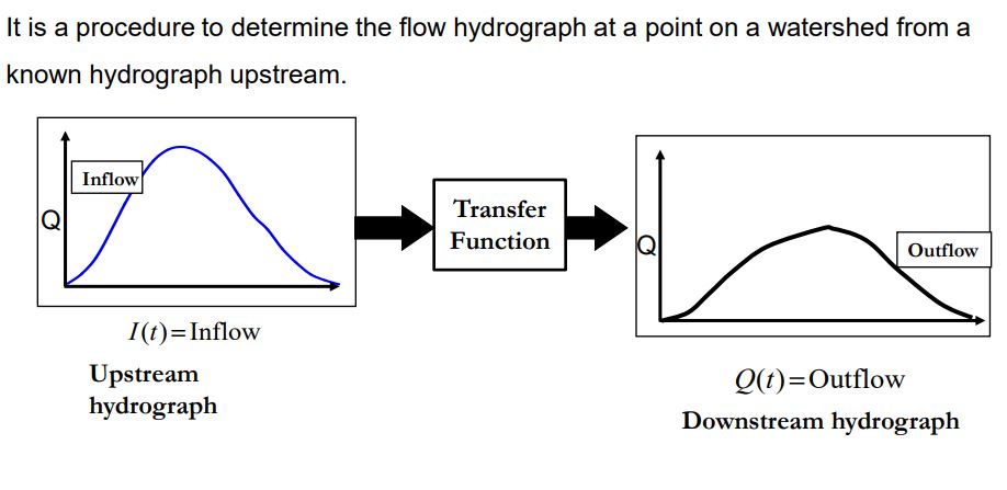
Flood routing is the technique of determining the flood hydrograph at a river’s section by utilizing the flood flow data at one or more upstream sections. The hydrologic analysis of problems such as flood forecasting, flood protection, reservoir design, and spillway design invariably includes flood routing. In these applications, two broad categories of routing can be recognized. These are:
- Reservoir routing In this type of routing analysis storage is a unique function of Outflow Discharge, i.e. S = f(Q)
- Channel routing In this type of routing analysis storage is a function of both Inflow and Outflow, here we use Muskingum Method
A variety of routing methods are available and they can be broadly classified into two categories:
Hydrologic Routing
Hydrologic-routing methods employ essentially the equation of continuity. In its simplest form, the inflow to the river reach is equal to the outflow of the river reach plus the change of storage:
I = O + ΔS/Δt
where
- I is average inflow to the reach during Δt
- O is the average outflow from the reach during Δt
- S is the water currently in reach (known as storage)
The hydrologic models (e.g. linear and nonlinear Muskingum models) need to estimate hydrologic parameters using recorded data in both upstream and downstream sections of rivers and/or by applying robust optimization techniques to solve the one-dimensional conservation of mass and storage-continuity equation.
Hydraulic Routing
Hydraulic methods, on the other hand, employ the continuity equation together with the equation of motion of unsteady.
Prism Storage It is the volume that would exist if the uniform flow occurred at the downstream depth. i.e., the volume formed by an imaginary plane parallel to the channel bottom drawn at the outflow section water surface.
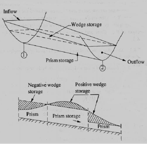
Wedge Storage It is the wedge-like volume formed between the actual water surface profile and the top surface of the prism storage.
S = Sp + Sw
Where,
- S = Total storage in the channel.
- Sp= Prism storage ⇒ f(Q) = function of outflow discharge.
- Sw= Wedge storage ⇒ f(I) = function of inflow discharge.
It can also be written as,
S = f(Q) + f(I)S = k[XIm + (1-X)Qm]
Where,
- X = Weighting factor
when X = 0
S = KQm (Function of Outflow)
- m = Constant
- = 0.6 for rectangular channels
- = 1.0, S = KQ (for nature channels/reservoirs)
- K = storage time constant
Flood Routing Analysis
Flood routing analysis is the process of the determination of the peak discharge of the flood and flow patterns of the flood. Flood routing analyses are carried out based on inflow and outflow hydrographs of a particular cross-section of the reservoir. It can be understood as given below.
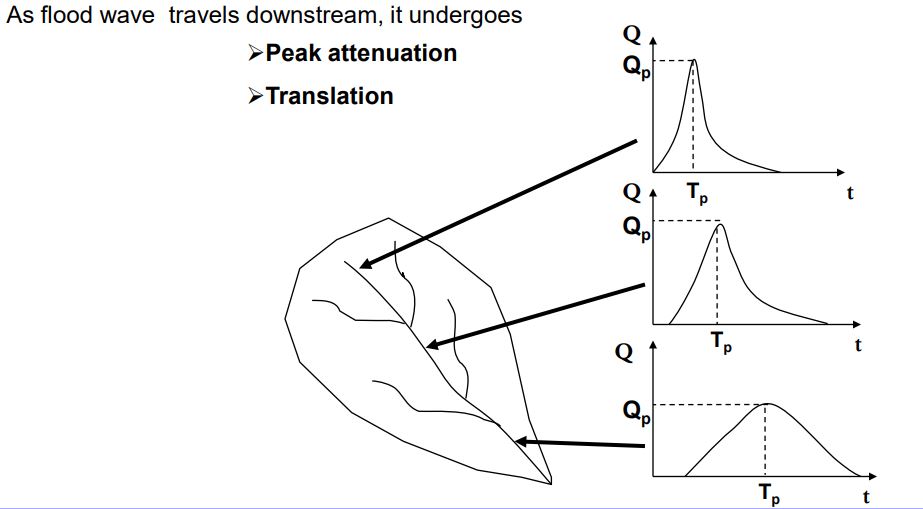
Attenuation – The peak of the outflow hydrograph will be smaller than of the inflow hydrograph. This reduction in the peak value is called attenuation.
Time Lag – The peak of the outflow occurs after the peak of the inflow; the time difference between the two peaks is known as lag. The attenuation and lag of a flood hydrograph at a reservoir are two very important aspects of a reservoir operating under flood-control criteria.
Muskingum Method of Channel Routing
The Muskingum method is a channel routing technique of flood routing. The Muskingum method uses the mass conservation approach of the inflow hydrograph.
We want to simulate the propagation of a flood wave along a channel. Storage is the function of both I and O.
Profiles of water flowing in a channel reach during the rising limb (a) and recession limb (b) of a flood wave
Assume that storage can be approximated as;
S = K[xI + (1 – x)O]
Where K[s] is a constant, and x is a weighting factor. K is approximately equal to the “residence time” of the flood wave within the stream reach. K has a unit of time and is a rough measure of the residence time of flood peak in the channel reach. A change in channel morphology may change the value of K.
The weighting factor x represents the degree of attenuation. For example;
(a) x = 0. In this case of a reservoir. i.e. Large attenuation.
(b) x = 0.5. In this case, S = K(I/2 + O/2). But we also have
(I1 + I2)/2 – (O1 + O2)/2 = (S2 – S1)/∆t
When ∆t = K, we can show that O2 = I1. The wave is simply translated with a lag time of K. i.e. No attenuation.
For most river channels, 0.1 < x < 0.3. The values of K and x have to be determined in each channel reach. One can measure I and O in the reach during a storm.
When a suitable value of x is used, the plot appears to follow a straight line. The slope of the straight line is K.
Once K and x are determined, we can route flood waves using the Muskingum method. The balance equation;
(I1 + I2)/2 – (O1 + O2)/2 = (S2 – S1)/∆t
But we also have
S2 – S1 = K[x(I2 – I1) + (1 – x) (O2 – O1)].
Combining the two equations and re-arranging terms,
O2 = C0 I2 + C1 I1 + C2 O1
where
- C0 = -(Kx – 0.5∆t)/(K – Kx + 0.5∆t)
- C1 = (Kx + 0.5∆t)/(K – Kx + 0.5∆t)
- C2 = (K – Kx – 0.5∆t)/(K – Kx + 0.5∆t)
From the above expression, it can be expressed as,
C0 + C1 + C2 = 1
Steps for calculation
(1) I is given for all time intervals. O is equal to I at t = 0.
(2) Determine K, x, C0, C1, and C2.
(3) Using I1, I2 and O1, calculate O2.
What is Reservoir Routing?
Reservoir routing is the technique of the estimation of the different flood parameters. In the reservoir routing technique, storage is a unique function of outflow discharge (Q or O).
∴ S = f (O)
The relationship is given by a discharge rating curve.
In reservoir routing, we re-arrange the balance equation;
(S2/∆t + O2/2) = (S1/∆t – O1/2) + (I1 + I2)/2
Given, I1, I2, and (S1/∆t – O1/2), we want to estimate the left-hand side.
The first step is to determine the relationships between the water stage (H), S and O. Topographic survey can be used to obtain the H-S relationship. Stream discharge measurement is conducted to determine the H-O relationship.
![Reservoir and Channel Routing [GATE Notes]](https://gs-post-images.grdp.co/2020/3/telegram_png30-1-img1585473029191-76.png-rs-high-webp.png)


