Time Left - 30:00 mins
GATE 2019: National Champion Test Digital Circuits
Attempt now to get your rank among 685 students!
Question 1
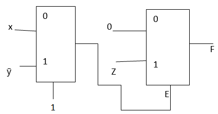
The Boolean function f implemented in the figure using two input multiplexers is
Question 2
A 16-bit ripple Carry adder is realized using 16 identical full adders (FA) as shown in the figure. The carry-propagation delay of each FA is 12 ns and the sum-propagation delay of each FA is 15 ns. The worst case delay (in ns) of this 16-bit adder will be __________. 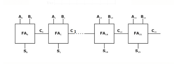
Question 3
A 4-bit shift register circuit configured for right-shift operation,
 , is shown. If the present state of the shift register is ABCD = 1101, the number of clock cycles required to reach the state ABCD = 1111 is _________.

Question 4
The digital multiplexer is basically a combination logic circuit to perform which of the following operations
Question 5
Output of a MOD 112 asynchronous down counter are connected to input of a 7 segment display as shown in figure below

The highest decimal number from 0-9 that can be displayed at 7 segment display is _______.
The highest decimal number from 0-9 that can be displayed at 7 segment display is _______.
Question 6
Consider the circuit given below.

The duty cycle of is
is
The duty cycle of
Question 7
By application of tensile force, the cross-sectional area of bar ‘P’ is first reduced by 30% and then by additional 25%. Another bar ‘Q’ of the same material is reduced in cross-sectional area by 50% in single step by applying tensile force. After deformation, the ratio of true strain in bar ‘P’ to bar ‘Q’ will be _____.
Question 8
consider the following circuits (assume all gates have a finite propagation delay)
1)
2)
3)
4)
Which of these circuits generate a periodic square wave output?
1)
2)
3)
4)
Which of these circuits generate a periodic square wave output?
Question 9
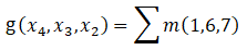
There are four Boolean variables  where x4 is MSB and x1 is LSB. The following function are defined on sets of them


then is
is
then
Question 10
A logic circuit consist of two 2 x 4 decoder as shown in figure

The output of the decoder are as follows:
Do = 1 when Ao = 0 and A1 = 0
D1 = 1 when Ao = 1 and A1 = 0
D2 = 1 when Ao = 0 and A1 = 1
D3 = 1 when Ao = 1 and A1 = 1
The value of f(x,y,z) is
The output of the decoder are as follows:
Do = 1 when Ao = 0 and A1 = 0
D1 = 1 when Ao = 1 and A1 = 0
D2 = 1 when Ao = 0 and A1 = 1
D3 = 1 when Ao = 1 and A1 = 1
The value of f(x,y,z) is
Question 11
For the circuit shown in the figure, the delays of NOR gates, multiplexers and inverters are 2 ns, 1.5 ns and 1 ns, respectively. If all the inputs P, Q, R, S and T are applied at the same time instant, the maximum propagation delay (in ns) of the circuit is_______.

Question 12
Assume that all the digital gates in the circuit shown in the figure are ideal, the resistor  and the supply voltage is 5V. The D flip-flops D1, D2, D3, D4 and D5, are initialized with logic values 0,1,0,1 and 0, respectively. The clock has a 30% duty cycle.

The average power dissipated (in mW) in the resistor R is_____
The average power dissipated (in mW) in the resistor R is_____
- 685 attempts
- 2 upvotes
- 1 comment
Jul 20ESE & GATE EC

