
- Home/
- GATE ELECTRICAL/
- GATE EE/
- Article
Three Phase A.C. Circuit Study Notes for GATE and Electrical Engineering Exams
By BYJU'S Exam Prep
Updated on: September 25th, 2023

Introduction to Three Phase A.C. Circuit
- A phase is carried out to the periodic modifications of a few quantities, which includes the voltage in an AC circuit.
- An electrical segment is measured in degrees, with 360° comparable to an entire cycle.
- A sinusoidal voltage is proportional to the cosine or sine of the section.
- Three-phase, abbreviated 3φ, refers to three different voltages and currents.
- It is a system produced by a generator that includes three sources that contain the same amplitude and frequency but out of phase from each other by 120°.
- The three phases should be supplied over six-wire, with two wires used for each phase. However, they are generally supplied over three wires
- The phase or line currents are the currents in each wire.
- AC Voltages and currents are expressed as RMS values
Download Formulas for GATE Electrical Engineering – Electromagnetic Theory
Table of content
- A phase is carried out to the periodic modifications of a few quantities, which includes the voltage in an AC circuit.
- An electrical segment is measured in degrees, with 360° comparable to an entire cycle.
- A sinusoidal voltage is proportional to the cosine or sine of the section.
- Three-phase, abbreviated 3φ, refers to three different voltages and currents.
- It is a system produced by a generator that includes three sources that contain the same amplitude and frequency but out of phase from each other by 120°.
- The three phases should be supplied over six-wire, with two wires used for each phase. However, they are generally supplied over three wires
- The phase or line currents are the currents in each wire.
- AC Voltages and currents are expressed as RMS values
Following requirements must be satisfied in order to be a alanced 3-phase set
- All 3 variables have the same amplitude
- All 3 variables have the same frequency
- All 3 variables are 120o in phase
Balanced System
Following requirements must be satisfied for a 3-phase system or circuit to be balanced.
- All 3 sources are represented by a set of balanced 3-phase variables.
- All loads are 3-phase with equal impedances(balanced load).
- Line impedances are equal in all 3 phases.
Formulas for GATE Electrical Engineering – Electrical Machines
Unbalanced System
A system is unbalanced if either the source is unbalanced or the load is unbalanced. Practically for an unbalanced system, the source is always balanced and the load is unbalanced.
Advantages of 3 Phase Circuits
- Electric power is generated and distributed in the three-phase system only.
- The instantaneous power in a three-phase system is always constant.
- The amount of wire required for a 3-phase system is lesser than that required for an equivalent 1-phase system.
- For Similar power, the three-phase system is more economical than the single-phase.
Formulas for GATE Electrical Engineering – Analog Circuits
Three-Phase Circuit Connections
- The Y or wye connection joints neutrals of each phase at a common junction.
- The Δ or delta connection is a triangle whose vertices form the buses, and there is no neutral bus available.
Star or “Y” (also known as the “T”) configuration:

- The star connection is made by connecting one end of each of phase windings together (as shown in the above figure).
- The voltage measured across a single winding or phase is known as the phase voltage.
- The voltage measured between the lines is known as the line-to-line voltage or simply as the line voltage.
- In a star connected system, the line voltage is greater than the phase voltage
- In a star connected system, phase current and line current are the same.
Delta, or Δ (also known as the “Pi,” or π) configuration:
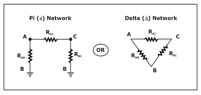
- In a delta connection, line voltage and phase voltage are the same.
- The line current of a delta connection is higher than the phase current
Balanced Three‐Phase Connections
- Y-Y connection
- Y-∆ connection
- ∆-∆ connection
- ∆-Y connection
Wye‐Delta transformation
- Wye-Delta transformation is also called as star-delta transformation.
- Wye-Delta Transformation is a technique to reduce common resistor connections that are neither in series nor on parallel.
- Conversion from Delta (Δ) to Wye (Y)
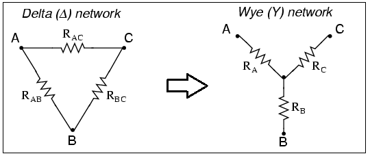


- Conversion from Wye (Y) to Delta (Δ)


Transformations
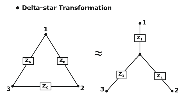


Note: Both Star Delta Transformation and Delta Star Transformation permits us to transform one sort of circuit connection into some other kind so as for us to without difficulty examine the circuit. These transformation strategies may be used to precise impact for star or delta circuits containing resistances or impedances.
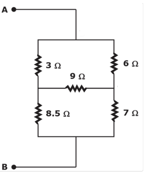
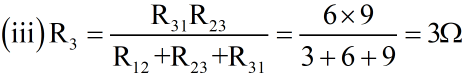
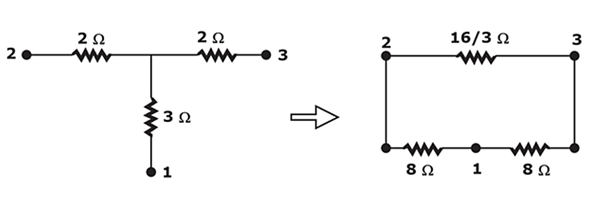
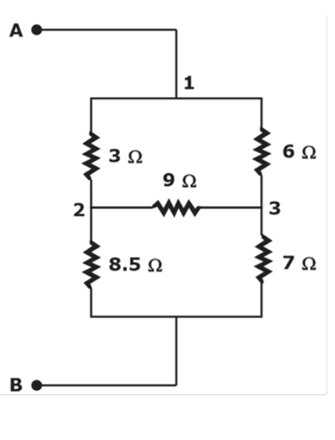 Delta to star transformation equations:
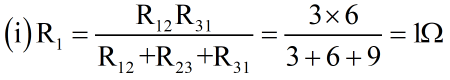

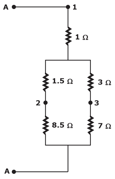
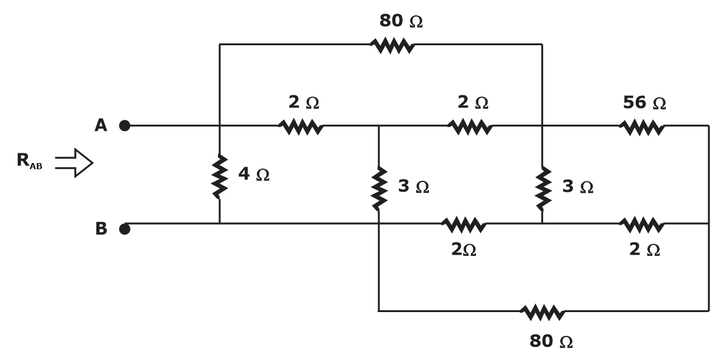
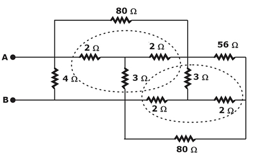
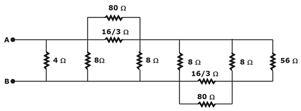
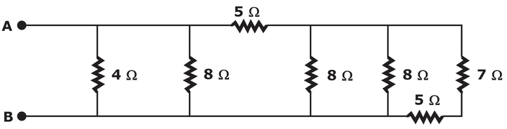
Now, it is easy to compute the total resistance between points A and B.
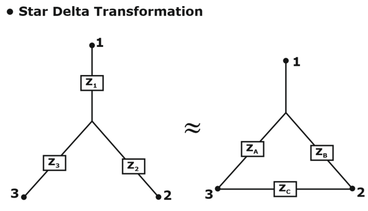
Star-Delta Transformation
Note: Both Star Delta Transformation and Delta Star Transformation allow us to convert one type of circuit connection into another type in order for us to easily analyze the circuit. These transformation techniques can be used to good effect for either star or delta circuits containing resistances or impedances.
Three-Phase Power:
If line values of voltage and current are known, the power (watts) of a purely resistive load is:
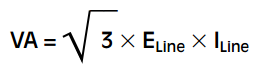
If the phase values of voltage and current are known, the apparent power is:
![]()
-
3 Phase A.C. Circuit- Part 1, Download PDF
-
3 Phase A.C. Circuit- Part 2, Download PDF
-
3 Phase A.C. Circuit- Part 3, Download PDF
The Three-Phase AC Circuit is an important topic for GATE EE, SSC JE EE, ESE IES EE, ISRO EE, and other electrical engineering exams.
For the detailed schedule of the GATE Electrical Engineering(EE) 2021 Champion Study Plan, click here
GATE Electrical Engineering(EE) 20221 Champion Study Plan
Click Here to Avail GATE EE Test Series!
Thanks


