
- Home/
- GATE MECHANICAL/
- GATE ME/
- Article
Cam: Definition, Types, Applications, Advantages and Disadvantages
By BYJU'S Exam Prep
Updated on: September 25th, 2023

A Cam is a mechanical device that converts rotary motion into reciprocating motion or vice versa. It is commonly used in internal combustion engines and other mechanical systems to convert the linear motion of the pistons into the rotary motion of the crankshaft or vice versa. Cams can be classified into two main types: oscillating and rotating.’
Cams PDF
Oscillating cams are typically used in reciprocating engines, such as those found in automobiles and motorcycles. These cams are typically shaped like a lobe and are mounted on a shaft that rotates as the engine runs. As the cam rotates, it pushes against a follower, which converts the rotary motion of the cam into reciprocating motion. On the other hand, rotating cams are typically used in continuous rotation systems, such as those found in machine tools and other industrial equipment. These cams are typically shaped like a disk and are mounted on a stationary shaft. As the cam rotates, it pushes against a follower, which converts the rotary motion of the cam into reciprocating motion.
Table of content
What is a Cam?
A mechanical device called a cam transforms rotational motion into linear motion or the opposite. It consists of a shaped surface that transmits motion between two mechanical parts. Cams are the most important part of the GATE ME syllabus and are commonly used in internal combustion engines and other mechanical systems to convert the linear motion of the pistons into the rotary motion of the crankshaft or vice versa.
Cam can also produce various types of motion, such as oscillating, reciprocating, and circular, depending on their shape and the specific application in which they are used. Cams can be classified into two main types: oscillating cams, which are mounted on a rotating shaft and rotating cams, which are mounted on a stationary shaft.
Working Principle of Cam
The working principle of a cam depends on its type and the specific application in which it is used. However, generally, a cam’s working principle involves converting rotary motion into linear or vice versa. In the case of an oscillating cam, the cam is mounted on a rotating shaft and is shaped like a lobe. As the shaft rotates, the cam pushes against a follower, which is a mechanical component that follows the shape of the cam. The follower converts the rotary motion of the cam into reciprocating motion, which can be used to perform various tasks such as opening and closing valves or activating a press.
In the case of a rotating cam, the cam is mounted on a stationary shaft and is shaped like a disk. As the cam rotates, it pushes against a follower, which converts the rotary motion of the cam into reciprocating motion. This can be used to perform tasks such as activating a press or moving a mechanical arm. Overall, a cam’s working principle involves using a shaped mechanical component that converts rotary motion into linear motion or vice versa, depending on the specific application in which it is used.
Types of Cam
There are several types of cams that are used in various mechanical systems. The Cam and Follower mechanism is a higher pair link mechanism and are asked in the GATE ME exam. Some common types of cams are listed below:
-
Oscillating cams: These are mounted on a rotating shaft and shaped like a lobe. They are used to convert the rotary motion of the shaft into reciprocating motion.
-
Rotating cams: These are mounted on a stationary shaft shaped like a disk. They are used to convert the rotary motion of the cam into reciprocating motion.
-
Flat cams: They are flat and used to produce a simple, back-and-forth motion.
-
Barrel cams: These cams are shaped like a barrel and are used to produce a circular motion.
-
Non-uniform cams: These have a non-uniform shape and are used to produce complex, irregular motions.
-
Harmonic cams: These are designed to produce a smooth, continuous motion.
-
Face cams: These are mounted on a rotating shaft’s face and are used to produce a linear motion.
-
Eccentric cams: These have an offset center of rotation and are used to produce an oscillating motion.
Overall, the type of cam used in a particular application depends on the specific requirements of the system and the type of motion that needs to be produced.
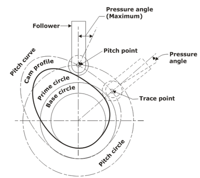
Terminologies of Cam
Cam terminologies describe cams’ various characteristics and features, which are mechanical components that convert rotary motion into linear or vice versa. These terms include the cam profile, which refers to the shape of the cam surface; the cam lobe, which is the raised portion of the cam that contacts the follower; and the cam follower, which is a mechanical component that follows the shape of the cam. Other important cam terminologies include the cam base circle, cam lift, cam throw, cam timing, and cam duration.
-
Cam profile: This refers to the shape of the cam surface, which determines the type of motion that the cam will produce.
-
Cam lobe: This refers to the raised portion of a cam that contacts the follower.
-
Cam follower: This mechanical component follows the cam’s shape and converts the cam’s rotary motion into linear or vice versa.
-
Cam base circle: This circle is formed by the points on the cam surface where the follower is in contact with the cam.
-
Cam lift: This is the distance that the cam lifts the follower as it rotates.
-
Cam throw: This is the distance the follower travels as the cam rotates.
-
Cam timing: This refers to the position of the cam in relation to the crankshaft or other reference point.
-
Cam duration: This is when the cam is in contact with the follower.
These terms describe the characteristics and behavior of cams in various mechanical systems.
Follower Displacement Diagram
A follower displacement diagram is a graphical representation of the motion of a cam follower as the cam rotates. It typically shows the position of the follower as a function of cam rotation and can be used to analyze the performance of a cam-follower system. A follower displacement diagram is typically used in the design and analysis of cam-based mechanisms and can be useful in predicting the motion of the follower under different operating conditions. The following terms are used concerning the angular motion of the cam.
- The angle of Ascent (ϕa): The angle through which the cam turns when the follower rises.
- The angle of Dwell (f) Angle of dwell is the angle through which the cam turns while the follower remains stationary at the highest or the lowest position.
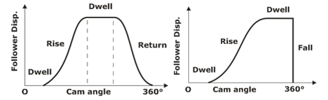
- The angle of Descent (ϕd): Angle of descent is the angle through which the cam turns while the follower returns to the initial position.
- The angle of Actions the total angle moved by the cam during the time between the beginning of the rise and the end of the return of the follower.
- In a specific time interval, acceleration must be given to consider the velocity.
- The dynamic effect of acceleration limit the speed, and the effect of a jerk (rate of change of acceleration) produce vibrations in the system.
- The angle made by the follower to the surface of the cam at the point of contact cannot be reduced from a certain value. So, it exerts minimum lateral pressure on the bearing.
- The size of the base circle controls the pressure angle.
Motion of the Follower
The motion of the follower in a cam-follower system is determined by the shape of the cam and the position of the follower relative to the cam. As the cam rotates, the follower follows the shape of the cam and is displaced in a specific direction. The motion of the follower can be linear, oscillating, or circular, depending on the cam’s shape and the follower’s position. The motion of the follower can also be affected by factors such as the cam lift and the cam throw, which determine the distance that the follower is displaced as the cam rotates. Understanding the follower’s motion is important in designing and analyzing cam-based mechanisms.
Uniform velocity or Constant Velocity
The follower’s constant velocity implies that the follower’s displacement is proportional to the cam displacement and the slope of the displacement curve is constant.
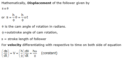
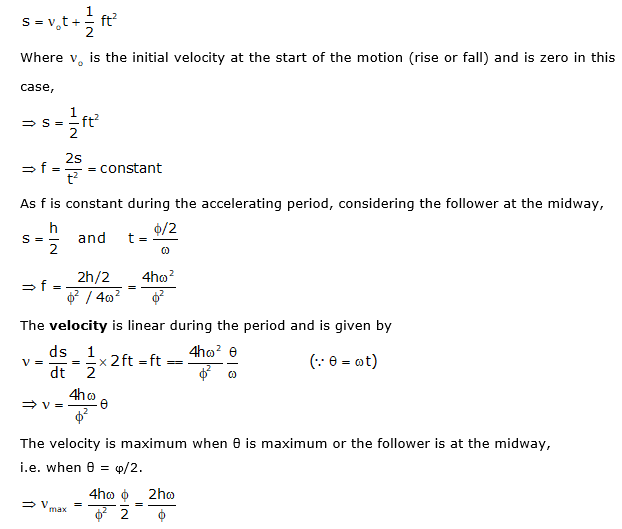
Uniform Acceleration and Retardation (Parabolic)
In such a follower program, there is acceleration in the first half of the follower motion, whereas deceleration during the later half. The displacement curve is found to be parabolic in this case. The magnitude of the acceleration and the deceleration is the same and constant in the two halves.
The equation for the linear motion with constant acceleration f (during the first half of the follower motion) is found as follows:
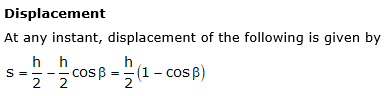
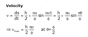
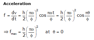
Simple Harmonic motion
This is a popular follower motion and is easy to lay out.
Let
- s = follower displacement (instantaneous)
- h = maximum follower displacement
- v = velocity of the follower
- f = acceleration of the follower
- θ = cam rotation angle (instantaneous)
- ϕ = cam rotation angle for the maximum follower displacement
- β = angle on the harmonic circle.
Applications of Cam
Cams are widely used in various applications to produce various types of motion. They are commonly used in internal combustion engines, machine tools, automation equipment, industrial equipment, and consumer products. Cams are versatile mechanical components that produce precise, repetitive motions and are essential in many mechanical systems.
-
Internal combustion engines: Cams are used in internal combustion engines to convert the linear motion of the pistons into the rotary motion of the crankshaft or vice versa.
-
Machine tools: Cams are used in machine tools to produce a variety of motions, such as oscillating, reciprocating, and circular.
-
Automation equipment: Cams are used in automation equipment to produce precise, repetitive motions.
-
Industrial equipment: Cams are used in various industrial equipment, such as pumps, compressors, and conveyors, to produce the necessary motion for the equipment to function.
-
Consumer products: Cams are used in various consumer products, such as appliances and toys, to produce motion.
Overall, cams are versatile mechanical components that are used in a wide range of applications to produce various types of motion.
Advantages of Cam
Cams are widely used in mechanical systems because they produce many linear, oscillating, and circular motions. They are also relatively simple and inexpensive to manufacture, making them cost-effective in various applications. There are several advantages to using cams in mechanical systems:
-
Cams can produce a wide range of linear, oscillating, and circular motions.
-
Cams are relatively simple and inexpensive to manufacture, making them cost-effective in various applications.
-
Cams are durable and have long lifespans, making them suitable for use in demanding environments.
-
Cams can transmit motion with high accuracy and precision, making them ideal for use in applications that require precise control.
-
Cams can operate at high speeds, making them suitable for high-speed mechanical systems.
Overall, cams are a reliable and cost-effective solution for producing various types of motion in mechanical systems.
Disadvantages of Cam
One of the main disadvantages of cams is that they cannot produce continuously variable motion, which limits their versatility in some applications. Cams are also less efficient than other mechanical components, such as gears, in transmitting motion. There are also some disadvantages to using cams in mechanical systems:
-
Cams cannot produce continuously variable motion, which limits their versatility in some applications.
-
Cams are not as efficient as other mechanical components, such as gears, in transmitting motion.
-
Cams are sensitive to wear and may require frequent maintenance or replacement if used in demanding environments.
-
Cams are not as precise as other mechanical components, such as ball screws, in producing linear motion.
-
Cams are not suitable for use in high-precision, high-accuracy applications due to the inherent tolerances in their manufacture.
While cams have some advantages, they also have some limitations that must be considered when selecting them for use in a particular application.
Get complete information about the GATE exam pattern, cut-off, and all those related things on the BYJU’S Exam Prep official youtube channel.


