There are three basic components in Linear Circuits:
- Resistance (R)
- Capacitance (C) and
- Inductance (L)
- An electrical system is said to be in steady-state when the variables describing its behaviour (voltages, currents, etc.) are either invariant with time (d.c. circuits) or are periodic functions of time (a.c. circuits).
- The time-varying currents and voltages resulting from the sudden application of sources, usually due to switching, are called transients.
- An electrical system is said to be in transient-state when the variables are changed non-periodically, i.e., when the system is not in steady-state.
- The transient response is the fluctuation in current and voltage in a circuit (after the application of a step voltage or current) before it settles down to its steady state.
Capacitance: the capacitance C between two opposite charged surfaces is defined by:
V = Q/C, where Q is the magnitude of the charge distributed on either surfaces, and V is the potential difference between the surfaces.
Differentiate V = Q/C using I = dQ/dt, We get dV/dt = I/C.
Inductance: The usual model for an inductor is a coil (solenoid). By Faraday’s Law of self‐inductance, a changing current in a coil induces a back electro‐motive force (emf) that opposes the change in current:
V = L. dI/dt, where V is the back emf across the inductor, dI/dt is the derivative of the current through the inductor and L is the inductance.
A first-order circuit can only contain one energy storage element (a capacitor or an inductor). The circuit will also contain resistance. So there are two types of first order circuits: RC circuit, and RL circuit.
Voltage-Current Relationships for Passive Elements

Element Transformations Resistor:
- Time Domain:

- s-Domain:

- Time Domain:
![]()


- s-Domain:
V(s) = L[sI(s) – i(0)]


- Time Domain:


- s-Domain:
i(s) = sCV(s) – Cv
![]()

- Identify the variable of interest (Inductor current for RL circuit, Capacitor voltage for RC circuit).
- Determine the initial value of the variable.
- Calculate the final value of the variable.
- Calculate the time constant for the circuit.
The analysis of circuits that contain combinations of resistors with capacitors or inductors follows the same general principles as for networks of resistors alone. Following figure shows a basic combination of a resistor with a capacitor, where a switch connected to a battery or ground allows the creation of voltage pulses at the input to the network.


We have 9 unknowns, using the above equations the following can be derived.
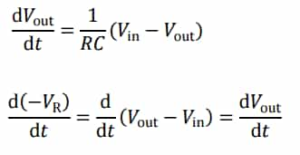
( We may assume the input voltage to be either 0 V or the battery emf E, and that it will be steady while the switch remains in a given position. During such periods, we may therefore treat Vin as a constant.)

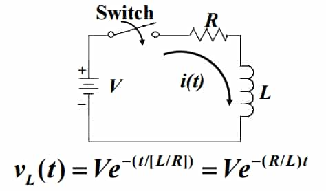
Transient Analysis of R-L Circuit:
- When the switch is closed, current flows into the capacitor.
- Current flow ceases when charge collected on the capacitor produces a voltage equal and opposite to V.
- An equation describing the behavior is shown; it is both exponential and asymptotic.
- In the equation, the value RC is called time constant (τ).
- As τ grows smaller, transient behavior disappears much faster.
where, iσ = Current through L at t → σ i.e., steady state current through L i0 = Current through L at t = 0 Req = Thevenin’s equivalent resistance seen across L for t > 0–
Transient Analysis of R-C Circuit:
- When the switch is closed, current flow is inhibited as the inductor develops an opposite voltage to the one applied.
- Current slowly begins to flow, as the inductor voltage falls toward 0.
- As the transient effect dies, current flow approaches V/R.
- The time constant τ in an RL circuit is defined as τ = L/R.
- As τ grows smaller, transient behavior disappears much faster.
The transient voltage across capacitor C at any time t:
where, Vσ = Voltage across capacitor at t → σ, i.e., steady state voltage across C Vσ = Voltage across C at t = 0– Req = Thevenin’s equivalent resistance seen across C for t > 0.
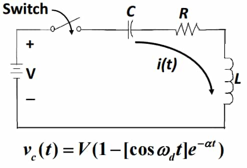
Transient Analysis of RLC Circuit:
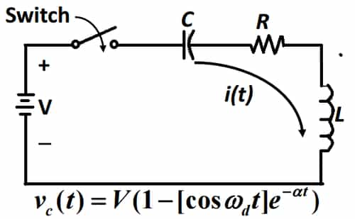
- A circuit with R, L, and C can exhibit oscillatory behavior if the components are chosen properly.
- For many values of R-L-C, there will be no oscillation.
- α is the damping factor, which determines the rate at which the oscillation dies out.
- The smaller L and C, the higher frequency the oscillation.
- If R is too large the quantity under the square root is negative, which means there is no oscillation


Comments
write a comment