- A periodic signal can be viewed as being composed of a number of sinusoids.
- Instead of specifying a periodic signal in terms of the time variable t, one can equivalently specify the amplitude and phase density of each sinusoid of frequency contained in the signal.
- It uses the frequency variable ω as an independent variable, and thus it is said to be the frequency domain of the given time domain signal.

- t-domain (time domain): i1(t)+i2(t)-i3(t)+i4(t)=0
- s-domain (complex frequency domain): I1(s)+I2(s)-I3(s)+I4(s)=0

- t-domain (time domain): -v1(t)+v2(t)+v3(t) = 0
- s-domain (complex frequency domain): -V1(s)+ V2(s)+V3(s) =0

- t-domain: v(t) = vs(t), and i(t) depends on circuit.
- s-domain: V(s) = Vs(s), and I(s) depends on circuit.
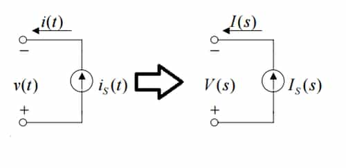
- t-domain: i(t) = is(t), and v(t) depends on circuit.
- s-domain: I(s) = Is(s), and V(s) depends on circuit.
Resonance: The circuit is said to be in resonance if the current is in phase with the applied voltage. Power factor of the circuit at resonance is unity. At resonance, the circuit behaves like a resistive circuit. The frequency at which the resonance occurs is called the resonant frequency.
There are two types of Resonance circuits: 1. Series Resonance circuit , and 2. Parallel Resonance circuit.
Series Resonance
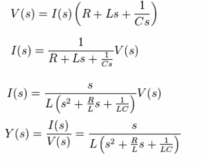
The series RLC can be analyzed in the frequency domain using complex impedance relations.

If the voltage source above produces a complex exponential waveform with complex amplitude V(s) and angular frequency s = σ + iω , KVL can be applied:
At resonance
|VL| = |VC| and these are 180° out of phase.
![]() (minimum)
(minimum)
 (maximum)
Zin = Input impedance
The frequency at which the reactances of the inductance and the capacitance cancel each other is the resonant frequency (or the unity power factor frequency) of this circuit.

Conditions for ω and ω0 in Series Resonance

Quality factor: Quality factor or Q-factor is basically a amplification factor for a resonant circuit.


Bandwidth: The bandwidth (ω2 – ω1) is called the half-power bandwidth or 3-dB bandwidth.


![]()
The bandwidth of the series circuit is defined as the range of frequencies in which the amplitude of the current is equal to or greater than(1/1.414) times its maximum amplitude. This yields the bandwidth B = ω2 - ω1 = R/L.
Frequency at which voltage across inductor is maximum

Frequency at which voltage across capacitor is maximum

Selectivity It is defined as the ratio of resonant frequency to the bandwidth.

Key Points
- Selectivity of series R-L-C circuit with C variable is
 .
. - Selectivity of series R-L-C circuit with L variable is also
- Higher the' selectivity, higher will be the quality factor.
- Higher the selectivity, lesser will be the bandwidth.
Parallel Resonance
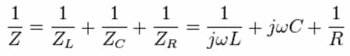
Parallel resonance circuit is also called anti-resonance circuit. The complex admittance of this circuit is given by adding up the admittances of the components:

At resonance,
- |iL| = |iC| and these are 180° out of phase
- (minimum)
- (maximum)
- (minimum)


where, 
[resonance frequency (rad/s)]
 [resonance frequency (Hz)]

Conditions for ω and ω0 in Series Resonance

A parallel RLC circuit is an example of a band-stop circuit response that can be used as a filter to block frequencies at the resonance frequency but allow others to pass.


Comments
write a comment