Time Left - 15:00 mins
GATE Prev Year : Networks Test-2
Attempt now to get your rank among 815 students!
Question 1
The circuit shown in Figure, with  has input voltage v(t) = sin2t. The resulting current i(t) is

has input voltage v(t) = sin2t. The resulting current i(t) is Question 2
The 2-port admittance matrix of the circuit shown is given by

Question 3
Let x (t) = a s (t) + s (–t) with s (t) = βe–4t u (t), where u (t) is unit step function. If the bilateral Laplace transform of x (t) is

Then the value of β is _________
Then the value of β is _________
Question 4
If R1 = R2 = R4=R and R3 = 1.1R in the bridge circuit shown in figure, then the reading in the ideal voltmeter connected between a and b is

Question 5
In the given circuit, the maximum power (in Watts) that can be transferred to the load RL is ________.

Question 6
A network is described by the state model as
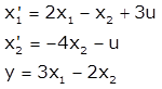
The transfer function H(s) is.
is.
The transfer function H(s)
is.- 815 attempts
- 8 upvotes
- 23 comments
Apr 11ESE & GATE EC

