Torsion of Shaft and Combined Stresses
Torsion means twisting a structural Member when it is loaded by couple that Produces rotation about longitudinal axis.
If ![]() be the intensity of shear stress, on any layer at a distance r from the centre of shaft, then
be the intensity of shear stress, on any layer at a distance r from the centre of shaft, then
![]()

Sign Convention
- Sign convention of torque can be explained by right hand thumb rule.
- A positive torque is that in which there is tightening effect of nut on the bolt. From either side of the cross-section. If torque is applied in the direction of right hand fingers than right hand thumbs direction represents movement of the nut.
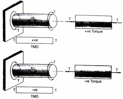
TMD = Torsion moment diagram
T = Torque
Rate of twist :![]()
Total angle of twist :![]()
Where, T = Torque,
J = Polar moment of inertia
G = Modulus of rigidity,
θ = Angle of twist
L = Length of shaft,
GJ = Torsional rigidity
![]() Torsional stiffness;
Torsional stiffness;
![]() Torsional flexibility
Torsional flexibility
![]() Axial stiffness;
Axial stiffness;
![]() Axial flexibility
Axial flexibility
Moment of Inertia About polar Axis:
- For solid circular shaft,:

- For hollow circular shaft:
Power Transmitted in the Shaft
- Power transmitted by shaft:
Where, N = Rotation per minute.
Compound Shaft
An improved type of compound coupling for connecting in series and parallel are given below
- Series connection: Series connection of compound shaft as shown in figure. Due to series connection the torque on shaft 1 will be equal to shaft 2 and the total angular deformation will be equal to the sum of deformation of 1st shaft and 2nd shaft.


Therefore,
Where,
θ1 = Angular deformation of 1st shaft
θ2 = Angular deformation of 2nd shaft
- Parallel connection: Parallel connection of compound shaft as shown in figure. Due to parallel connection of compound shaft the total torque will be equal to the sum of torque of shaft 1 and torque of shaft 2 and the deflection will be same in both the shafts.


Therefore,![]()
Strain energy (U) stored in shaft due to torsion:
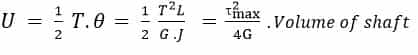
- G = Shear modulus
- T = Torque
- J = Moment of inertia about polar axis
Effect of Pure Bending on Shaft
The effect of pure bending on shaft can be defined by the relation for the shaft,

![]()
Where, σ = Principal stress
D = Diameter of shaft
M = Bending moment
Effect of Pure Torsion on Shaft
It can be calculated by the formula, which are given below

![]()
Where, τ = Torsion
D = Diameter of shaft
Combined effect of bending and torsion

- Principal stress
- Maximum shear stress
- Equivalent bending moment :
- Equivalent torque
Shear Stress Distribution:
- Solid Circulation Section:

- Hollow Circulation Section
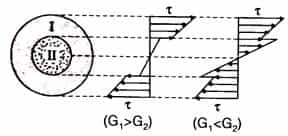
- Composite Circular Section
- Thin Tubular section: In view of small thickness shear stress is assumed to be uniform


Comments
write a comment