Time Left - 01:00:00 mins
GATE EC Networks : National Champion Test
Attempt now to get your rank among 627 students!
Question 1
The condition on R, L and C such that the step response y(t) in figure has no oscillations, is

Question 2
An amplifier with resistive negative feedback has two left half-plane poles in its open-loop transfer function. The amplifier
Question 3
Le the signal f(t) = 0 outside the interval T1, T2 where T1 and T2 are finite. Furthermore,  . The region of convergence (ROC) of the signal’s bilateral Laplace transform F(s) is
1. A parallel strip containing the jΩ axis
2. A parallel strip not containing the jΩ axis
3. The entire s-plane
4. A half plane containing the jΩ axis
1. A parallel strip containing the jΩ axis
2. A parallel strip not containing the jΩ axis
3. The entire s-plane
4. A half plane containing the jΩ axis
Question 4
Consider a delta connection of resistors and its equivalent star connection as shown below. If all elements of the delta connection are scaled by a factor k, k > 0, the elements of the corresponding star equivalent will be scaled by a factor of

Question 5
The thevenin’s equivalent of a circuit operating at w = 5 rad/s, has Vµ = 3.71 ∠−15.9° V and Z0 = 2.38 – j 0.667 Ω. At this frequency, the minimal realization of the Thevenin’s impedance will have a
Question 6
For maximum power transfer between two cascaded sections of an electrical network, the relationship between the output impedance Z1 of the first section to the input impedance Z2 of the second section is
Question 7
If 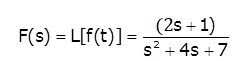 then the initial and final values of f(t) are respectively
then the initial and final values of f(t) are respectivelyQuestion 8
The minimum number of equations required to analyze the circuit shown in below is

Question 9
In the circuit shown in the figure, the value of capacitor C (in mF) needed to have critically damped response i(t) is ________.

Question 10
In the circuit shown, at resonance, the amplitude of the sinusoidal voltage (in Volts) across the capacitor is ________.

Question 11
A continuous time LTI system is described by

Assuming zero initial conditions, the response y(t) of the above system for the input x(t)=e–2tu(t) is given by
Assuming zero initial conditions, the response y(t) of the above system for the input x(t)=e–2tu(t) is given by
Question 12
In what range should Re(s) remain so that the laplace transform of the function e(a+2)t+5 exists.
Question 13
The circuit shows a current source where mesh current containing current source is equal to current of current source i.e. I2 = Is .

The value of current I1 will be:
The value of current I1 will be:
Question 14
In the given circuit, the maximum power (in Watts) that can be transferred to the load RL is ________.

Question 15
In the circuit shown, what value of RL the maximum power is delivered to RL?

Question 16
Find the Thévenin equivalent against 7k ohm resistor in circuit shown?

Question 17
In the AC network shown in the figure, the phasor voltage VAB (in Volts) is:

Question 18
In the circuit shown, VC is 0 volts at t = 0 sec. For t > 0, the capacitor current ic(t), where t in seconds, is given by

Question 19
The following arrangement consists of an ideal transformer and an attenuator which attenuates by a factor of 0.8. An ac voltage VWX1 100 V is applied across WX to get an open circuit voltage VYZ1 across YZ. Next, an ac voltage VYZ2 = 100 V is applied across YZ to get an open circuit voltage VYZ2 across WX. Then  are respectively

Question 20
Two magnetically uncoupled inductive coils have Q factors q1 and q2 at the chosen operating frequency. Their respective resistances are R1 and R2. When connected in series, their effective Q factor at the same operating frequency is
Question 21
An LC tank circuit consists of an ideal capacitor C connected in parallel with a coil of inductance L having an internal resistance R. The resonant frequency of the tank circuit is
Question 22
The driving point impedance of the following network

is given by . The component values are
is given by
Question 23
The ABCD parameters of the following 2-port network are

Question 24
The derivative of the symmetric function drawn in figure will look like

Question 25
For the circuit shown in Figure, the initial conditions are zero. Its transfer function  is
is

is Question 26
Let x (t) = a s (t) + s (–t) with s (t) = βe–4t u (t), where u (t) is unit step function. If the bilateral Laplace transform of x (t) is

Then the value of β is _________
Then the value of β is _________
Question 27
Three capacitors C1 C2 and C3 whose values are 10 µF. 5 µF. and 2 µF respectively, have breakdown voltages of 10V, 5V, and 2V respectively. For the interconnection shown below, the maximum safe voltage in Volts that can be applied across the combination, and the corresponding total charge
in µC stored in the effective capacitance across the terminals are respectively,

in µC stored in the effective capacitance across the terminals are respectively,
Question 28
An AC source of RMS voltage 20 V with internal impedance Zy = (1+2j) Ω feeds a load of impedance ZL = (7 + 4j) Ω is the figure below. The reactive power consumed by the load is

Question 29
In the following figure, the Thevenin's equivalent pair (voltage, impedance), as seen at theterminals P-Q, is given by

Question 30
For the circuit shown in figure, Thevenin’s voltage and Thevenin’s equivalent resistance at terminals a – b is

- 627 attempts
- 3 upvotes
- 32 comments
Jun 15ESE & GATE EC

