Time Left - 20:00 mins
GATE EC : Analog Circuits Champion Quiz 3
Attempt now to get your rank among 628 students!
Question 1
Assuming the OP-AMP to be ideal, the voltage gain of the amplifier shown below is

Question 2
An ideal op-amp is an ideal
Question 3
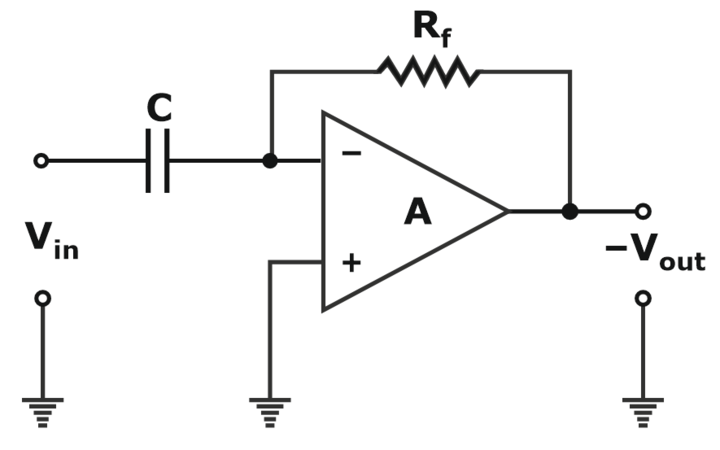
Assume that the op-amp of Fig. is ideal. If Vi is a triangular wave, then V0 will be
Question 4
The circuit in Figure is a

Question 5
The pole-zero plot given below corresponds to a

Question 6
Noise with uniform power spectral density of N0W/Hz is passed through a filter  followed by an ideal low pass filter of bandwidth B Hz. The output noise power in watts is
Question 7
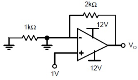
If the op-amp in the below figure, has an input offset voltage of 5 mV and an open-loop voltage gain of 10,000, then v0 will be

Question 8
The Op-amp circuit shown in figure is a filter. The type of filter and its cut-off frequency are respectively.

Question 9
Consider the following circuit using an ideal OPAMP. The I-V characteristics of the diode is described by the relation  where
where  and V is the voltage across the diode (taken as positive for forward bias)

For an input voltage V = –1V, the output voltage V0 is
where For an input voltage V = –1V, the output voltage V0 is
Question 10
Assuming that the opamp in the circuit shown below is ideal, the output voltage V0 (in volts) is______
- 628 attempts
- 2 upvotes
- 31 comments
Apr 21ESE & GATE EC

