For the unity feedback system, the given system What will be the transfer function in the network shown below?
Question 2
An open loop system represented by the Transfer Function is
Question 3
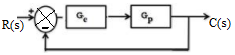
The system shown in the figure is
Question 4
The Bode plot of a Transfer Function G (5) is shown in the figure below. The gain (20 log|G(s)|) is 32 dB and -8 dB at 1 rad/s and 10 rad/s respectively. The phase is negative for all ω. Then G (s) is
Question 5
The gain margin of a unity feedback control system with the open loop transfer function G(s) = is
Question 6
A system with transfer function is excited by sin (ωt). The steady-state output of the system is zero at
Question 7
For the signal-flow graph shown in the figure, which one of the following expressions is equal to the transfer function ?
Question 8
For a tachometer if θ(t) is rotor displacement is radians, e(t) is the output voltage and Kt is the tachometer constant in V/rad/sec, then the transfer function, will be
Question 9
A control system is defined by the following mathematical relationship The response of the system as t→ is
Question 10
The Transfer Function of the circuit shown below is
Question 11
A unity feedback system has an open loop transfer function, . The root locus plot is
Question 12
The transfer function of a second-order real system with a perfectly flat magnitude response of unity has a pole at (2 – j3). List all the poles and zeroes.
Question 13
Figure shows a feedback system where K > 0. The range of K for which the system is stable will be given by
Question 14
The system with A = is
Question 15
Consider the following Nyquist plot of loop transfer function over ω = 0 to ω = ∞. Which of these plot’s represents a stable closed loop system.
Question 16
What will be the corner frequency, in Hz, for the system shown?
Question 17
The feedback system shown below oscillates at 2 rad/s when
Question 18
In the signal flow diagram given in the figure u1 and u2 are possible inputs possible inputs whereas y1 and y2 are possible outputs. When would the SISO system derived from this diagram be controllable and observable?
Question 19
The following equation defines a separately excited dc motor in the form of a differential equation The above equation may be organized in the state–space form as follows Where the P matrix is given by
Question 20
The state variable description of a linear autonomous system is X = AX, where X is the two-dimensional state vector and A is the system matrix given by The roots of the characteristic equation are
Question 21
For the system with u as unit impulse and with zero initial state, the output y, becomes
Question 22
The transfer functions of two compensators are given below: Which one of the following statements is correct?
Question 23
The system is to be compensated such that its gain-crossover frequency becomes same as its uncompensated phase-crossover frequency and provides a 45o phase margin. To achieve this, one may use
Question 24
The transfer functions of two compensators are given below: Which one of the following statements is correct?
Question 25
The Laplace transform of a function f(t) is F(s) = As t →∞, f(t) approaches
Question 26
The block diagram of a closed loop control system is given by figure. The values of K and P such that the system has a damping ratio of 0.7 and an undamped natural frequency ωn of 5 rad/sec, are respectively equal to
Question 27
Which is correct about control system block diagram?
Question 28
The asymptotic Bode magnitude plot of a minimum phase transfer function is shown in the figure. This transfer function has
Question 29
For the equation If X(0)=0, & X'(0)= 0 then the solution x(t) approaches the following values at t →∞
Question 30
The block diagram shown in figure gives a unity feedback closed loop control system. The steady state error in the response of the above system to unit step input is


 is
is 
 ?
? 
 will be
 of the circuit shown below is
 . The root locus plot is
 is
is


 The roots of the characteristic equation are

 As t →∞, f(t) approaches


 If X(0)=0, & X'(0)= 0 then the solution x(t) approaches the following values at t →∞

