In the circuit shown below what is the output voltage (Vout) in Volts if a silicon transistor Q and ideal op-amp are used?
Question 2
Which statement is not correct in terms of negative feedback amplifier?
Question 3
Consider the circuit shown in the figure. In this circuit R = 1 kΩ and C = 1 μF. The input voltage is sinusoidal with a frequency of 50 Hz, represented as a phasor with magnitude Vi and phase angle 0 radian as shown in the figure. The output voltage is represented as a phasor with magnitude V0 and phase angle δ radian. What is the value of the output phase angle δ (in radian) relative to the phase angle of the input voltage?
Question 4
The complete set of only those Logic Gates designated as universal Gates is
Question 5
The phase sequence of a three-phase alternator will reverse if
Question 6
The op-amp shown in the figure has a finite gain A = 1000 and an infinite input resistance. A step voltage Vi = 1 mV is applied at the time t = 0 as shown. Assuming that the operational amplifier is not saturated, the time constant (in millisecond) of the output voltage V0 is
Question 7
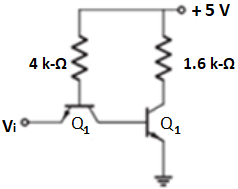
A TTL NOT gate circuit is shown in the figure. Assuming VBE = 0.7 V of both the transistors, if Vi = 3.0 V of both the transistors, if Vi = 3.0V, then the states of the two transistors will be
Question 8
Consider the inverting amplifier, using an ideal operational amplifier shown in the following figure. The designer wishes to realize the input resistance seen by the small-signal source to be as large as possible, while keeping the voltage gain between-10 and -25. The upper limit on RF is 1 MΩ. The value of R1 should be
Question 9
In the active filter circuit shown in figure, if Q = 1, a pair of poles will be realized with ω0 equal to
Question 10
Which statement describes op-amp running in open-loop configuration that amplifies signal?