Time Left - 25:00 mins
GATE EE 2018 Exams: Digital Circuits Quiz 3
Attempt now to get your rank among 866 students!
Question 1
Fig. shows a 4 to 1 MUX to be used to implement the sum S of a 1–bit full adder with input bits P and Q and the carry input Cin. Which of the following combinations of inputs to I0, I1, I2 and I3 of the MUX will realize the sum S?

Question 2
In the 4 × 1 multiplexer, the output F is given by F = A ⊕ B. Find the required input ‘I3I2I1I0’.

Question 3
The output Y of the logic circuit given below is:![]()
Question 4
When two 16-input multiplexers drive a 2- input MUX, what is the result?
Question 5
In the 4 × 1 multiplexer, the output F is given by F = A ⊕ B. Find the required input ‘I3I2I1I0’.

Question 6
A 4 × 1 MUX is used to implement a 3–input Boolean function as shown in figure. The Boolean function F (A, B, C) implemented is

Question 7
The output Y of a 2-bit comparator is logic 1 whenever the 2-bit input A is greater than the 2-bit input B. The number of combinations for which the output is logic 1, is
Question 8
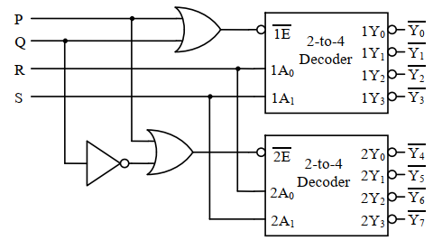
A 1–to–8 demultiplexer with data input Din, address inputs S0, S1, S2 (with S0 as the LSB) and  to
to  as the eight demultiplexed output, is to be designed using two 2–to–4 decoders (with enable input
  and address input A0 and A1) as shown in the figure Din, S0, S1 and S2 are to be connected to P, Q, R and S, but not necessarily in this order. The respective input connections to P, Q, R and S terminals should be
Question 9
A one bit full adder takes 75 nsec to produce sum and 50 nsec to produce carry. A 4 bit parallel adder is designed using this type of full adder. The maximum rate of additions per second can be provided by 4 bit parallel adder is Ax106 additions/sec. The value of A is _____ .
Question 10
A binary full-subtractor.
- 866 attempts
- 3 upvotes
- 38 comments
Jul 20ESE & GATE EE

