Time Left - 15:00 mins
Achiever Study Plan ESE-2018: Electrical Circuits Quiz 4
Attempt now to get your rank among 300 students!
Question 1
The RC circuit shown in the figure is

Question 2
The switch in the circuit shown was on position a for a long time and is moved to position b at time t = 0. The current i(t) for t > 0 is given by

Question 3
In the circuit shown the average value of the voltage Vab (in Volts) in steady state condition is ______

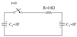
Question 4
In the circuit shown, the initial voltages across the capacitors C1 and C2 are 1V and 3V, respectively. The switch is closed at time t = 0. The total energy dissipated (in Joules) in the resistor R until steady state is reached is ________
Question 5
Consider the following statements S1 and S2
S1: At the resonant frequency the impedance of a series R-L-C circuit is zero.
S2: In a parallel G-L-C circuit, increasing the conductance G results in increase in its Q factor.
Which one of the following is correct?
S1: At the resonant frequency the impedance of a series R-L-C circuit is zero.
S2: In a parallel G-L-C circuit, increasing the conductance G results in increase in its Q factor.
Which one of the following is correct?
Question 6
For the R-L circuit shown in Figure, the input voltage v i(t) = u(t). The current i(t) is

- 300 attempts
- 1 upvote
- 6 comments
Feb 2ESE & GATE EE

