Time Left - 08:00 mins
DMRC 2018 Electrical Engineering : Quiz 12
Attempt now to get your rank among 625 students!
Question 1
Below figure shows a switched-capacitor converter comprising of two capacitors.

When switch 1 is closed, the capacitors are connected in series, and when the switch 2 is closed, they are connected in parallel. The output voltage produced is:
When switch 1 is closed, the capacitors are connected in series, and when the switch 2 is closed, they are connected in parallel. The output voltage produced is:
Question 2
A step voltage wave of magnitude 1.4pu travelling along a lossless transmission line that terminates in a capacitor (∴inductive reactance is zero). What will be the voltage magnitude across capacitor at the instant travelling wave reaches capacitor –
Question 3
If direct axis reactance Xd and quadrature axis reactance Xq are equal, then reluctance power is
Question 4
The saturation value of a.c. collector current for an amplifier with an a.c. collector resistance of  and Q-point values of
  and
and  is
is
Question 5
Two point charges are placed on x-axis. A  charge is at x = 10 cm and
  charge is at x = 40 cm. What is the potential at x = 100 cm from the origin?
Question 6
The equivalent capacitance of two capacitors in parallel is four time their equivalent capacitance in series. This means that
Question 7
A load is connected to a circuit. At the terminals to which the load is connected,  The maximum power supplied to the load is
Question 8
A 24 V battery of internal resistance  is connected to a variable resistor. At what value of current drawn from the battery is the heat produced in the resistor maximum?
Question 9
A lead compensating network
(a) Improves response Time
(b) Stabilize the system with low phase margins
(c) Enables moderating increase in gain without affecting stability
(d) Increase resonant frequency
(a) Improves response Time
(b) Stabilize the system with low phase margins
(c) Enables moderating increase in gain without affecting stability
(d) Increase resonant frequency
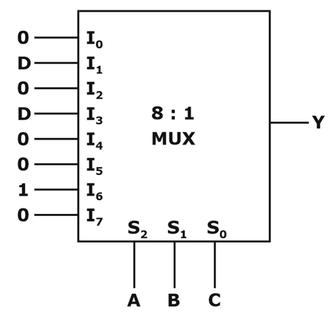
Question 10
An 8-to-1 multiplexer is used to implement a logical function Y as shown in the figure. The output Y is given by
- 625 attempts
- 3 upvotes
- 8 comments
Tags :
ESE & GATE EEGeneralJul 10ESE & GATE EE

