Time Left - 40:00 mins
GATE EE 2019: ThunderBolt Quiz 3 (App update required to attempt this test)
Attempt now to get your rank among 624 students!
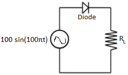
Question 1
In the circuit shown in the figure, Load Resistacne RL=10Ω, & the diode used is ideal. The input power factor is _______.
Question 2
Determine the output voltage of the summing amplifier, If V1=0.2V and V2=0.5V.
Question 3
A system block diagram is shown in the given figure.

The overall transfer function of the system is

The value of X would be equal to
The overall transfer function of the system is
The value of X would be equal to
Question 4
Consider the following figure of Nyquist plot regarding gain margin and phase margin.
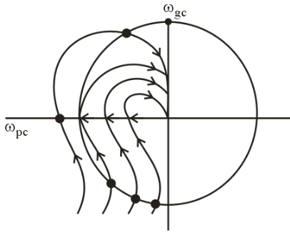
The gain margin of unity feedback system having forward transfer function is
is
The gain margin of unity feedback system having forward transfer function
Question 5
How many different output state the following shift register is having, if the initial state is (Q3 Q2 Q1 Q0)= 0001

Question 6
A DC series motor running a friction load at 1000 r.p.m takes 40 A from a 240 V supply mains. Its field resistance is 0.2 Ω and that of the armature is 0.25 Ω. If a diverter of 0.3 Ω resistance is put in parallel with the series field winding find the motor speed. Assume the field flux to be proportional to field current.
Question 7
In a 3 phase 4 pole, 50Hz salient pole synchronous machine the armature reluctance mmf changes with
Question 8
If  the circulation of the vector field F around the closed path shown in the figure is __________ (Take direction to be anti-clockwise as positive).

Question 9
In an electro dynamic instrument the total resistance of the voltage coil circuit is 6800 Ω and the mutual inductance changes uniformly from -103 μH at zero deflection to +105 μH at full scale. The angle of full scale being 80°. If a potential difference of 80 V is applied across the voltage circuit and a current of 2 A at a power factor of 0.45 is passed through the current coil, what will be the deflection. Spring constant of the instrument is 3.36 × 10 -6 N-m/rad.
Question 10
The single phase half bridge voltage inverter as shown in figure has an output frequency of 50 Hz. It uses unipolar pulse width modulation with switching frequency of 50 kHz and modulation index of 0.For Vin=50V DC, L=5.56 mH, C=6.58  , R=10Ω the amplitude of fundamental component in the output voltage under steady state is
, R=10Ω the amplitude of fundamental component in the output voltage under steady state is

Question 11
Calculate the total active power for the below 3-ϕ circuit

Given that line to line voltage is 10V _______W
Question 12
For the given figure obtain the h12 parameter

Question 13
In case ICS=80A , VCC=220V, tON=1.5 μs and toff=4 μs for the switching wave forms shown in the figure, find the average power loss in the power transistor for a switching frequency of 2 kHz.

Question 14
For a power diode, the reverse recovery time is 3.9 μs and the rate of diode current decay is 50 A/ μs. For a softness factor of 0.3, calculate the storage charge?
Question 15
The neutral of a three phase Y connected alternators is solidly grounded as shown in the figure. A fault occurs on the phase a and the current in this phase is found to be 100A . The positive sequence component of current in phase b is

- 624 attempts
- 3 upvotes
- 1 comment
Tags :
ESE & GATE EEGeneralJun 9ESE & GATE EE

