Time Left - 30:00 mins
GATE EC 2020 National Champion Quiz: Network Theory (App update required to attempt this test)
Attempt now to get your rank among 513 students!
Question 1
Consider the following figure

The current Is in Amps in the voltage source and voltage Vs in Volts across the current source respectively, are
The current Is in Amps in the voltage source and voltage Vs in Volts across the current source respectively, are
Question 2
If 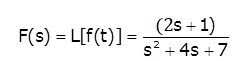 then the initial and final values of f(t) are respectively
then the initial and final values of f(t) are respectivelyQuestion 3
The transfer function  of the circuit shown below is

of the circuit shown below is Question 4
Calculate Thevenin’s resistance Rth(in Ω) across terminals A and B:

Question 5
The transmission parameter A for the circuit is

Question 6
Consider the two-port network given below

Y parameter Y11in ‘s’ domain for the network is
Y parameter Y11in ‘s’ domain for the network is
Question 7
If R1 = R2 = R4=R and R3 = 1.1R in the bridge circuit shown in figure, then the reading in the ideal voltmeter connected between a and b is

Question 8
A 5H inductor, which has a resistance of 30Ω, a 3.7 µF and a 90Ω non inductive resistor are connected in series to a 200V, 50Hz, 1-phase supply. The time interval between the positive peak value of the supply voltage and the next peak value of power
Question 9
A certain practical DC voltage source can provide a current of 2.5 A when its terminals are short circuited, and can provide a power of 80 W to 20 Ω load. The maximum power it could deliver to a well-chosen load resistance RL is __________ W.
Question 10
In the network shown in the given figure, the switch s is closed at t = 0 with the capacitor uncharged, the value of  at
at  will be

Question 11
The steady state is obtained with S open. Initially, S is closed. Determine the value of the current I at t=0+. The circuit is given below.

Question 12
Consider the two port network shown below:

The voltage gain ![]() will be
will be
- 513 attempts
- 6 upvotes
- 1 comment
Oct 5ESE & GATE EC

