Time Left - 55:00 mins
GATE 2020: Toppers Quiz 26 (App update required to attempt this test)
Attempt now to get your rank among 386 students!
Question 1
In a transformer core loss found 60 W at 30 Hz and 100 W at 40 Hz. Calculate the core loss at 50 Hz if all the losses being measured at same flux densities.
Question 2
Find the output of a discrete-time LTI system is given by the discrete time convolution su
Y[n] =
Y[n] =
Question 3
A transmission line having a reactance of 3 pu is operating at  3 pu. The generator is connected at source end which is delivering 2 pu of active power. Find the load angle?
Question 4
A single-phase fully controlled rectifier is supplying a load with an anti-parallel diode as shown in the figure. All switches and diodes are ideal. Which one of the following is true for instantaneous load voltage and current?

Question 5
Two transformers each rated 250 KVA, 15/2 kV and 50 Hz are connected in open Delta on both primary and secondary. A Delta connected three phase load of 250 KVA, 0.8 pf 2kV is connected to the low voltage terminals of the open delta transformer. Transformer current on the 15 kV side of this connection is
Question 6
The circuit using BJT with β = 50 and VBE = 0.7 V, the collector voltage VC will be

Question 7
Let the z -transform of a signal be given as
![]()
then the value of x[3] is _________.
Question 8
A 100kVA, 415V, Y-connected synchronous machine generates rated open circuit voltage of 415V at a field current of 15A. The short circuit armature current at a field current of 10A is equal to its rated armature current. The saturated synchronous impedance in p.u., if armature resistance is 0.1pu is
Question 9
Determine the total gain of the given circuit, if 

Question 10
The over current relays for the line protection and loads connected at the buses are shown in the figure.
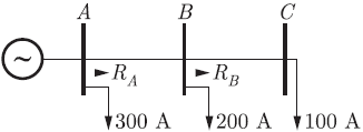
The relays are IDMT in nature having the characteristic top.
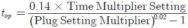
The maximum and minimum fault currents at bus B are 2000 A and 500 A respectively. Assuming the time multiplier setting and plug setting for relay RB to be 0.1 and 5 A respectively, the operating time of RB (in seconds) is_____.
The relays are IDMT in nature having the characteristic top.
The maximum and minimum fault currents at bus B are 2000 A and 500 A respectively. Assuming the time multiplier setting and plug setting for relay RB to be 0.1 and 5 A respectively, the operating time of RB (in seconds) is_____.
Question 11
For an instrument transformer: Accuracy class is the maximum allowable percentage composite error in Measured value.
Which of the following is impermissible value of measured current for 100 A of primary current in metering CT of Accuracy class 0.1?
Which of the following is impermissible value of measured current for 100 A of primary current in metering CT of Accuracy class 0.1?
Question 12
A three-phase half-wave controlled rectifier circuit is shown in the figure. It is operated from 3-ϕ star-connected, supply transformer with a line to line ac supply voltage of 440 volts rms, at 50 Hz. The thyristors are triggered at a delay angle of α=30o. Assume continuous ripple-free current.

The average output current is _______ A.
The average output current is _______ A.
Question 13
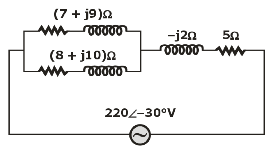
The average power consumed by the circuit shown below is
Question 14
A 3000 kVA, 6 – pole, 50 Hz, 3 – phase synchronous generator is connected to an infinite bus of 3300 V. synchronous reactance of the machine is 0.85 Ω/phase and generator is running at 1200 rpm. Calculate the excitation voltage (E ) and load angle (δ ) –
Question 15
The open loop transfer function of a unity feedback system and root locus plot for the system is shown below.
![]()

The range of K for which the system has damped oscillatory response is
Question 16
A single phase full converter, connected to 230 V, 50 Hz source, is feeding a load R = 10 Ω in series with a large inductance that makes the load current ripple free. For a firing angle of 45 ° the reactive power input is ________ VAR.
Question 17
Find the input resistance Rin of the circuit shown in figure below:

Question 18
If  is the Fourier transform of
  and
and  is the Fourier transform of
  and
and  then
then  in terms of
  is
is
Question 19
The shaft output of a three-phase 50- Hz induction motor is 50 KW. The friction and windage losses are 720 W, the stator core loss is 3200 W and the stator copper loss is 1500 W. The rotor current and rotor resistance referred to stator are respectively 55 A and 0.25 Ω. If the slip is 1.5%, what is the percentage (%) efficiency?
Question 20
Determine Vo and ID2 respectively for the two-diode circuit with parameters R1 = 5 kΩ, R2 = 10 kΩ, VT = 0.7 V, V+ = 5 V, and V— = —5 V and Vi = 4 V

Question 21
The block diagram of a control system is shown below
The region in the K-versus α-plane in which the system to be asymptotically stable is
Question 22
A 4-bit shift register circuit configured for right shift operation is shown below. If the present state of the shift register is ABCD = 1000, the number of pulses required to reach the state ABCD = 1111 is

Question 23
An alternator has an internal voltage of E1 = 1.8 p.u. and X = 0.8 p.u. is connected to a synchronous motor with internal voltage of E2 = 1.2 p.u. and X = 0.6 p.u. The reactance of the line connecting the alternating to the motor is 0.4 p.u. When the generator supplies 1 p.u. power Calculate the rotor angle (in Degree) difference between two machines –
Question 24
The root-locus of a unity feedback system is shown below:

The open loop transfer function is
Question 25
In the circuit shown below,

If the inductor current is assumed to be continuous then the average current through the diode for the duty cycle 0.5 is _________ A.
If the inductor current is assumed to be continuous then the average current through the diode for the duty cycle 0.5 is _________ A.
- 386 attempts
- 0 upvotes
- 2 comments
Tags :
ESE & GATE EEGeneralApr 15ESE & GATE EE

