GATE 2020: Toppers Quiz 27 (App update required to attempt this test)
Attempt now to get your rank among 257 students!
Question 1
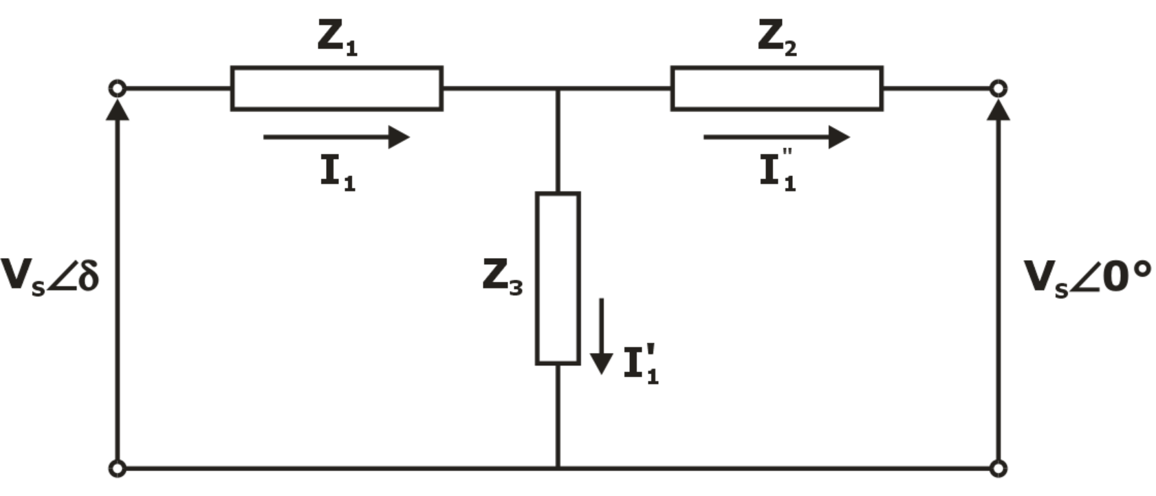
For the given figure I1=1 - j2 , I1' = -2 - j5 Calculate the power factor at the receiving end
Question 2
A self commutating switch SW, operated at duty cycle δ is used to control the load voltage as shown in the figure Under steady state operating conditions, the average voltage across the inductor and the capacitor respectively are.
Question 3
The starting current of 3 phase Induction motor is 7 times the rated current while the rated slip is 6%. The ratio of starting torque to full load torque is –
Question 4
If the load of 50 MW is suddenly applied then find the frequency deviation during this time when A 200 MVA alternator operated at no load at frequency of 50 Hz, it has inertia constant of 5 MWsec/MVA and governing system has a time delay of 0.6 sec.?
Question 5
Below figure shows the torque-slip characteristics of a 3-phase induction motor. It displays the motor operating in 3 modes: motoring, generating and braking. Determine the slip of the rotor in the generating mode.
Question 6
Which of the following is the laplace transform of cos(at)sinh(at)?
Question 7
In the chopper circuit shown in figure, the input dc voltage has a constant value Vs. The output voltage V0 is assumed ripple free. The switch S is operated with a switching time period T and a duty ratio D. What is the value of critical inductance (LC) at the boundary of continuous and discontinuous conduction of the inductor current iL?
Question 8
Two transformers are to be operated in parallel such that they share load in proportion to their kVA ratings. The rating of the first transformer is 1000 kVA ratings. The rating of the first transformer is 1000 kVA and its pu leakage impedance is 0.08 pu. If the rating of second transformer is 350 kVA, its pu leakage impedance is
Question 9
For the block diagram shown below, the limiting value of K for stability of inner loop is found to be X < K < Y. The overall system will be stable if and only if
Question 10
The function shown in the figure can be represented as
Question 11
An SCR has Vg-Ig characteristics given as Vg = 1.5 + 8 Ig. In a certain application, the gate voltage consists of rectangular pulses of 12 V and of duration 50 μs with duty cycle 0.2. The value of Rg series resistor in gate circuit to limit the peak power dissipation in the gate to 5 watts is
Question 12
A combinational circuit using 4 x 1 multiplexer is shown in the following diagram. The simplified expression for Z is
Question 13
An 8-pole, 50 Hz, 3-phase induction motor has a power input of 72 kW. The motor is running at a speed of 700 rpm. Determine the mechanical power developed, if the total stator loss is 800 W.
Question 14
The root locus plot for a control system is shown below:
Consider the following statements regarding the system.
1) System is stable for all positive value of K.
2) System has real and repeated poles for 0.573 < K < 7.464.
3) System has damped oscillatory response for all values of K greater than 0.573.
4) System is overdamped for 0 < K < 0.573 and K > 7.464.
Which of the following is/are correct?
Question 15
The corona loss on a particular system at 50 Hz is 2 KW/km/ph. The corona loss at 60 Hz would be ________ KW/km/ph.
Question 16
For the given NPN transistor hfe = 100. The output voltage (V0) is
Question 17
A six pulse cyclo-converter, fed from 3-phase, 400 V, 50 Hz source, is delivering a load current of 40 A to a single-phase resistive load. The source has an inductance of 1.2 mH per phase. The rms value of load voltage for firing angle delay of 0 ° is _________.
Question 18
For the given multi-diode circuit shown in figure below, assume that VT = 0.7 V for each diode. Then what is the value of ID2 and Vo respectively
Question 19
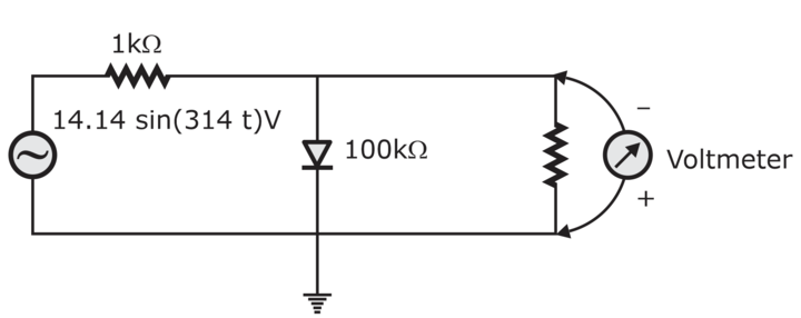
The input impedance of the permanent magnet moving coil (PMMC) voltmeter is infinite. Assuming that the diode shown in the figure below is ideal, the reading of the voltmeter in Volts is
Question 20
The two-stage amplifier shown in fig uses transistors Q1 and Q2, both having current gain β of 80 and dynamic emitter resistance, r’e, of 25 Ω each. Find out the overall voltage gain of the amplifier.
Question 21
A DC generator has a useful flux of 0.05 Wb per pole. It has 8 lap connected poles and has 600 conductors on the armature. It runs at a speed of 1200 rpm. Find the EMF generated and the speed required if same connections are made using wave winding?
Question 22
A current transformer with a bar primary has 300 turns in its secondary winding. The resistance & reactance of secondary circuit are 1.5 Ω’s and 1Ω respectively including transformer winding. With a 5A current flowing in a secondary winding the magnetizing MMF is 100 Amps and the iron losses is 1.2 watts. Determine R
Question 23
If the given signal x(n) = (3()-4())u(n) then find the z-tranform of the given signal?
Question 24
In a two-element series circuit, the voltage applied is v(t)=100sin(100πt) V and the current supplied in i(t)=6sin(100πt + 30°) A, then identify the elements
Question 25
If the Converter shown in figure has a purely resistive load of R and the delay angle is The rectification efficiency and Form Factor (F.F) respectively are