Flow-through Pipes
Major Loss: It is calculated by Darcy Weisbach formulas
Loss of head due to friction

where,
L = Length of pipe,
v = Mean velocity of flow
d = Diameter of pipe,
f = Coefficient of friction
 friction factor

For turbulent flow, coefficient of friction

Chezy’s Formula: In fluid dynamics, Chezy’s formula describes the mean flow velocity of steady, turbulent open channel flow.
 v= c √mi, c= Chezy's Constant = √(8g/f)
i = Loss of head per unit length of pipe
![]() (hydraulic slope tan θ)
(hydraulic slope tan θ)
m = Hydraulic mean depth
![]()
Relation between Coefficient of Friction and Shear Stress

We get ![]()
where,
f = Coefficient of friction
τ0 = Shear stress
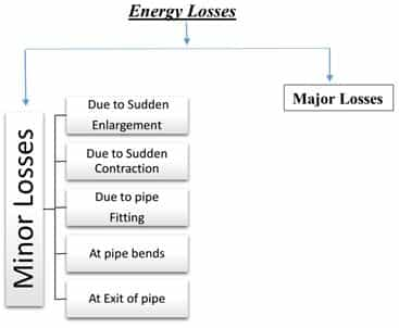
Minor Loss:
The another type of head loss in minor loss is induced due to following reasons
Loss due to Sudden Enlargement
Head loss 
Loss due to Sudden Contraction
Head loss, hL = 0.5 v22/ 2g
Remember v2 is velocity at point which lies in contracted section.
Loss of Head at Entrance to Pipe
Head loss, 
Loss at Exit from Pipe
Head loss, 

Note: In case 1 and 2, flow occurs between pipe to pipe, while in case 3 and 4, flow occurs between tank and pipe. We are taking entry or exit w.r.t. pipe. So, be careful.
Combination of Pipes: Pipes may be connected in series, parallel or in both. Let see their combinations.
Pipe in Series: As pipes are in series, the discharge through each pipe will be same.

Q = A1v1 = A2v2 = A3v3
Total loss of head = Major loss + Minor loss
![]()
Major loss = Head loss
due to friction in each pipe

While, minor loss = Entrance loss + Expansion loss + Contraction loss + Exit loss

If minor loss are neglected then,


Pipes in Parallel: In this discharge in main pipe is equal to sum of discharge in each of parallel pipes.

Hence, Q = Q1 + Q2
Loss of head in each parallel pipe is same

where, ![]() and
and ![]() are head loss at 1 and 2 respectively.
are head loss at 1 and 2 respectively.
Equivalent Pipe: A compound pipe which consists of several pipes of different lengths and diameters to be replaced by a pipe having uniform diameter and the same length as that of compound pipe is called as equivalent pipe.

(where, L = L1 + L2 + L3)
If f = f1 = f2 = f3
Then,

Hydraulic Gradient Line (HGL) and Total Energy Line (TEL)

HGL → It joins piezometric head (p/ρg + z) at various points.
TEL → It joins total energy head at various points:
{(p/ρg + z) + v2/2g}
Note: HGL is always parallel but lower than TEL.
Power Transmission through Pipe (P)


Power delivered by a given pipe line is maximum when the flow is such that one third of static head is consumed in pipe friction. Thus, efficiency is limited to only 66.66%
Maximum efficiency, ![]()
Water Hammer: When a liquid is flowing through a long pipe fitted with a vale at the end of the pipe and the valve is closed suddenly a pressure wave of high intensity is produced behind the valve. This pressure wave of high intensity is having the effect of hammering action on the walls of the pipe. This phenomenon is known as water hammer.
Intensity of pressure rise due to water hammer,
![]()
When valve is closed gradually when valve closed suddenly with rigid pipe.
![]()
When valve closed suddenly with plastic pipe

If the time required to close the valve
![]() Valve closure is said to be gradual.
Valve closure is said to be gradual.
![]() The valve closure is said to be sudden.
The valve closure is said to be sudden.
Where,
L = Length of pipe
D = Diameter of pipe
C = Velocity of pressure wave produced due to water hammer ![]()
v = Velocity of flow
K = Bulk modulus of water
E = Modulus of elasticity for pipe material.
t = Time required to choose the valve.
If you are preparing for ESE/ GATE or other PSU Exams (Civil Engineering), then avail Online Classroom Program for ESE and GATE CE:
Online Classroom Program for ESE/GATE CE(20+ Courses and 180+ Mock Tests)
You can avail of BYJU'S Exam Prep Test Series specially designed for all AE & JE Exams:
BYJU'S Exam Prep Test Series AE & JE (160+ Mock Tests)
You can avail of BYJU'S Exam Prep Test Series specially designed for all Civil Engineering Exams:
BYJU'S Exam Prep Test Series ESE/GATE CE (180+ Mock Tests)
Thanks
Sahi Prep Hai To Life Set Hai.


Comments
write a comment